Thermocouple vs. Thermistor: Which Temperature Sensor is Right for You?
Oct 15, 2026Updated 15 October 2026: rewritten with tolerance figures per temperature, published response-time data and a selection table. Reviewed by the Focusens Engineering Team.
| Property | NTC thermistor | Thermocouple (type K) | PT100 RTD, for reference |
|---|---|---|---|
| How it works | Resistance falls as temperature rises | Voltage set by the temperature difference between the measuring junction and the cold junction | Resistance rises almost linearly |
| Typical range | -40 to 125 °C for coated parts (Vishay NTCLE100E3); up to 250 °C glass-encapsulated (TDK G1541) | -200 to about 1200 °C; the usable top end depends on sheath size and material (TC Direct) | -200 to 850 °C (IEC 60751) |
| Tolerance at 25 °C | ±0.23 °C (±1 % R25, ±1 % B) | ±1.5 °C, class 1 | ±0.20 °C, class A |
| Tolerance at 100 °C | ±1.30 °C (same part) | ±1.5 °C, class 1 | ±0.35 °C, class A |
| Signal at 25 °C | 10 kΩ, changing about 4.4 % per °C | Around 40 µV per °C | About 0.39 Ω per °C |
| What the input needs | A bias resistor or current, plus a table or Steinhart-Hart fit | Cold-junction compensation and a microvolt input | A small constant current, 3- or 4-wire for accuracy |
| Lead wire | Ordinary copper; at 10 kΩ the leads hardly matter | Thermocouple or matching extension wire all the way to the input | Copper, but lead resistance counts on 2-wire |
The NTC figures are our calculation for a 10 kΩ, B = 3950 part; the method is in the next section.
An NTC thermistor's error comes from two tolerances: the resistance at 25 °C (R25) and the B value that sets the curve. At 25 °C only the R25 tolerance counts. Away from 25 °C the B tolerance adds in, so the error grows in both directions. TDK and Vishay both describe the spread this way.
A thermocouple's tolerance is fixed by class in IEC 60584-1:2013: for type K class 1 it is ±1.5 °C from -40 to 375 °C, then ±0.4 % of the temperature. The standard is clear that these tolerances apply to the wire as delivered and do not include drift in use. Neither do they include the instrument's cold-junction compensation error, which adds on top in a real system.
| Temperature | 10k NTC, ±1 % R25, ±1 % B | 10k NTC, ±1 % R25, ±0.5 % B | Type K class 1 | Type K class 2 | Type T class 1 | PT100 class A |
|---|---|---|---|---|---|---|
| -40 °C | ±0.65 | ±0.39 | ±1.5 | ±2.5 | ±0.5 | ±0.23 |
| 0 °C | ±0.42 | ±0.30 | ±1.5 | ±2.5 | ±0.5 | ±0.15 |
| 25 °C | ±0.23 | ±0.23 | ±1.5 | ±2.5 | ±0.5 | ±0.20 |
| 50 °C | ±0.54 | ±0.40 | ±1.5 | ±2.5 | ±0.5 | ±0.25 |
| 85 °C | ±1.05 | ±0.69 | ±1.5 | ±2.5 | ±0.5 | ±0.32 |
| 100 °C | ±1.30 | ±0.83 | ±1.5 | ±2.5 | ±0.5 | ±0.35 |
| 125 °C | ±1.75 | ±1.07 | ±1.5 | ±2.5 | ±0.5 | ±0.40 |
| 150 °C | ±2.24 | ±1.35 | ±1.5 | ±2.5 | ±0.6 | ±0.45 |
All values in ± °C. NTC: beta model with B = 3950, worst-case combination of the two tolerances, our calculation. Thermocouples: IEC 60584-1:2013 as reproduced by TC Direct. PT100: IEC 60751 class A, valid from -100 °C wire-wound and from -30 °C thin-film. For the NTC against a PT100 alone, see our RTD vs thermistor comparison.
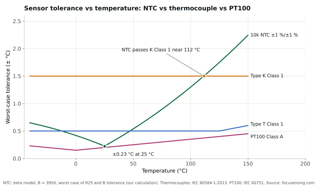
Three things follow from the table. Up to about 110 °C a ±1 % NTC is tighter than a class 1 type K thermocouple, and by 125 °C it is not. A class 1 type T thermocouple (±0.5 °C up to 125 °C) beats the same NTC outside roughly -10 to 45 °C. And if you need ±0.5 °C all the way from -50 to 150 °C, neither sensor here gets there; a wire-wound PT100 class A does, since thin-film class A starts at -30 °C.
The rule of thumb that thermocouples are fast and thermistors slow, or the reverse, is not a safe guide. Below are step tests from room-temperature air into boiling water, timed to 63.2 % of the step. The thermocouples alone span a factor of 100, and the only NTC tested the same way is a stainless-capped probe, so the table compares packages more than principles:
| Construction | Time constant | Source |
|---|---|---|
| Mineral-insulated thermocouple, 0.5 mm, insulated junction | 0.03 s | TC Direct |
| Mineral-insulated thermocouple, 1.5 mm, insulated junction | 0.3 s | TC Direct |
| Mineral-insulated thermocouple, 3.0 mm, insulated junction | 0.8 s | TC Direct |
| Mineral-insulated thermocouple, 6.0 mm, insulated junction | 3.0 s | TC Direct |
| Sheathed thermocouple, 1/8 in, grounded junction | 0.34 s | JMS Southeast |
| Sheathed thermocouple, 1/8 in, ungrounded junction | 1.6 s | JMS Southeast |
| NTC in a stainless steel cap (Vishay NTCAIMME3) | 13-16 s | Vishay datasheet |
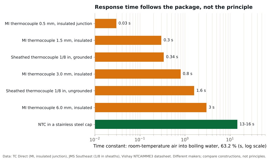
Two other published figures use different tests, so they do not belong in the same table: a coated radial NTC (Vishay NTCLE100E3) responds in about 1.2 s in oil, and a glass-encapsulated NTC (TDK G1541) has a thermal cooling time constant of about 4.5 s in air. Both are bare sensors, not probes.
What drives the result is mass and the thermal path. TC Direct puts a grounded junction at roughly half the time of an insulated one; JMS measured a wider gap, 0.34 s against 1.6 s on a 1/8 in sheath. JMS also warns that no real process matches a boiling-water test, so use these numbers to compare constructions, not to predict your own process. Shrink the package and either sensor gets faster; put either one in a thick stainless tube and it slows down.
Coated NTC thermistors such as the Vishay NTCLE100E3 are rated -40 to 125 °C continuously and 150 °C for short periods. Glass-encapsulated parts like the TDK G1541 go to 250 °C. The housing often sets a lower limit than the element: the stainless-capped Vishay probe in the table above is rated -25 to 110 °C.
A type K thermocouple has class tolerances defined up to 1000 °C (class 1) and 1200 °C (class 2), but the usable maximum depends on the construction. TC Direct rates type K mineral-insulated cable with an Inconel 600 sheath at 1150 °C for 6 mm, 1070 °C for 3 mm and 700 °C for 1 mm, and at 800 °C with a 304, 321 or 316L stainless sheath of 1.5 mm or more.
An NTC gives a large signal, about 4.4 % per °C at 25 °C for B = 3950, so a simple divider into an ADC works. The catch is the curve: TDK notes that the simple B-value model is only accurate over a limited range around 25 °C, and wider ranges need the Steinhart-Hart equation or the maker's table. Our 10k thermistor chart lists the common 10k curves, and the B-value guide explains why they differ.
The measuring current also heats the thermistor. Vishay gives a dissipation constant of 7 mW/K for the NTCLE100E3 and TDK about 0.45 mW/K in air for the glass G1541, so the same 0.1 mW raises them by about 0.014 K and 0.22 K (our calculation, power divided by the dissipation factor). Keep the power low on small glass parts.
A thermocouple needs no excitation and does not self-heat, but its signal is tiny, around 40 µV per °C for type K near room temperature, and it measures a difference: the input has to know the temperature at its own terminals. If that compensation is off, the reading is off by the same amount; the cold-junction article linked above covers it in millivolts. Run thermocouple or matching extension wire all the way to the input, and test a suspect probe as described in how to test a thermocouple with a multimeter.
| Application | First choice | Why |
|---|---|---|
| -40 to 125 °C, best accuracy near room temperature | NTC thermistor | ±0.23 °C at 25 °C for a ±1 % part (our calculation) and a signal of about 4.4 % per °C |
| Up to 150-250 °C | Glass-encapsulated NTC, or PT100 | Coated NTCs stop at 125-150 °C |
| -50 to 500 °C with a tight, standard curve | PT100 or PT1000 | One IEC 60751 curve for every maker. Class A holds to 450 °C wire-wound or 300 °C thin-film, and class B covers -50 to 500 °C in either construction |
| Above about 500 °C, or a very thin, fast probe | Thermocouple, type K or N | Range, and mineral-insulated probes down to 0.5 mm |
| Motor winding over-temperature trip | PTC thermistor (switching) | A threshold device built for relays; see motor PTC thermistors |
The full PT100 resistance table is on its own page, the RTD basics are in the RTD guide, and switching PTCs for motors are covered in PTC motor thermistor for winding protection.
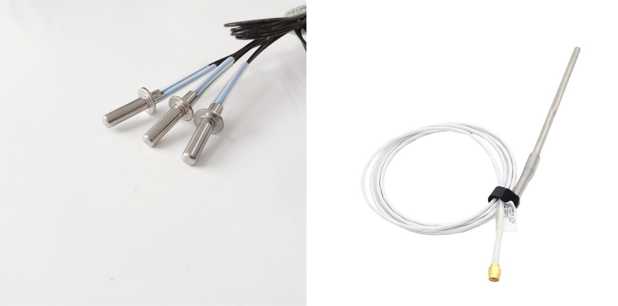
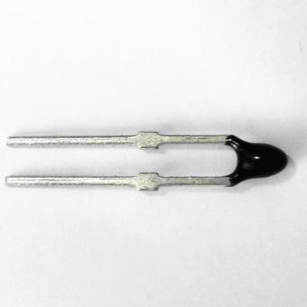
An NTC thermistor is a ceramic resistor whose resistance falls as it warms; you read it with a small current. A thermocouple is two different metals joined at the tip; it produces a voltage set by the difference between the tip and the instrument terminals. The NTC is more accurate near room temperature and gives a much bigger signal. The thermocouple covers far higher temperatures.
A narrow range, about -40 to 125 °C for common coated parts and 250 °C for glass ones; a non-linear curve that needs a table or the Steinhart-Hart equation; error that grows away from 25 °C; and self-heating if the measuring current is too high.
It depends on the construction. In TC Direct's boiling-water test a 0.5 mm mineral-insulated thermocouple with an insulated junction reaches 63.2 % in 0.03 s, a 3 mm one in 0.8 s and a 6 mm one in 3.0 s. TC Direct puts a grounded junction at about half those times.
Measure it at a known temperature and compare with the maker's R-T table: about 10 kΩ at 25 °C for a 10k NTC. Open or near-zero readings mean a broken or shorted part. The full procedure is in how to test an NTC thermistor, and for PTCs in how to test a PTC thermistor.
A thermocouple is a sensor: it produces a small voltage that depends on temperature. A thermostat is a switch or controller that acts on a temperature, such as turning a heater on and off at a set point. Gas appliances blur the line, because the pilot thermocouple's own output holds the gas safety valve open; see thermopile vs thermocouple for how that differs from a thermopile.
Focusens makes NTC thermistor probes, high-precision NTC thermistors, RTD sensors and thermocouple sensors. Send us the range, accuracy, housing and cable length, and we will suggest the sensor type that fits.
No.1 XiSan Road, Electromechanical Industry Park , High&New Tech.Zone. Hefei,Anhui,China
тел : +86-551-69109668
Whatsapp : +86-13339100504
Эл. адрес : info@focusens.com
Skype : melodyliu520






 +86-551-69109668