KTY84 replacement: the four things that break when you cross-reference
Sep 14, 2026The KTY silicon sensors are being withdrawn, and the designs that used them are now being re-sourced under a deadline. Siemens states in its own product note that the KTY sensor is discontinued and no longer available in the market, and TI publishes an end-of-life replacement note for the KTY81 and KTY82.
Most of what is published about this is a table of "equivalent" part numbers. That table is useful, and we publish one ourselves in the KTY83-110 cross-reference guide.
It is also the part of the job least likely to cause a field failure. The four problems below are the ones that come back after the new parts are already fitted.
Nearly every other thermistor on your bench is quoted at 25 °C. KTY81 and KTY83 follow that habit: R25 = 1000 Ω or 2000 Ω. KTY84 does not. Its 1000 Ω figure is the value at 100 °C.
At 25 °C a KTY84/130 sits at about 603 Ω. If an engineer reads "1 kΩ" on a KTY84 line and pairs it with a 1 kΩ part specified at 25 °C, the two curves are roughly 40 % apart at room temperature. The bridge still reads something. It reads the wrong thing.
These are the published values for a KTY84/130 at a 2 mA sense current, with the tolerance NXP states in kelvin at each point. Note how the tolerance widens at the top of the range.
| Temperature (°C) | Min (Ω) | Typ (Ω) | Max (Ω) | Tolerance (K) |
|---|---|---|---|---|
| -40 | 340 | 359 | 379 | ±6.48 |
| 0 | 474 | 498 | 522 | ±6.07 |
| 25 | 577 | 603 | 629 | ±5.84 |
| 50 | 694 | 722 | 750 | ±5.59 |
| 100 | 970 | 1000 | 1030 | ±4.90 |
| 150 | 1282 | 1334 | 1385 | ±7.10 |
| 200 | 1641 | 1722 | 1803 | ±9.71 |
| 250 | 2046 | 2166 | 2286 | ±12.73 |
| 300 | 2456 | 2624 | 2791 | ±22.12 |
KTY84/130 at a 2 mA sense current, from Table 7 of the NXP KTY84 series data sheet. The 1000 Ω nominal appears at 100 °C, not 25 °C.
The practical check takes one minute: put the candidate part and the original on the same bench at room temperature and compare readings before anything is soldered. A 40 % gap is visible immediately.
KTY84 runs to 300 °C. That is why it ended up in motor windings, spindles and brake-adjacent sensing in the first place. It is also the specification that no drop-in successor matches.
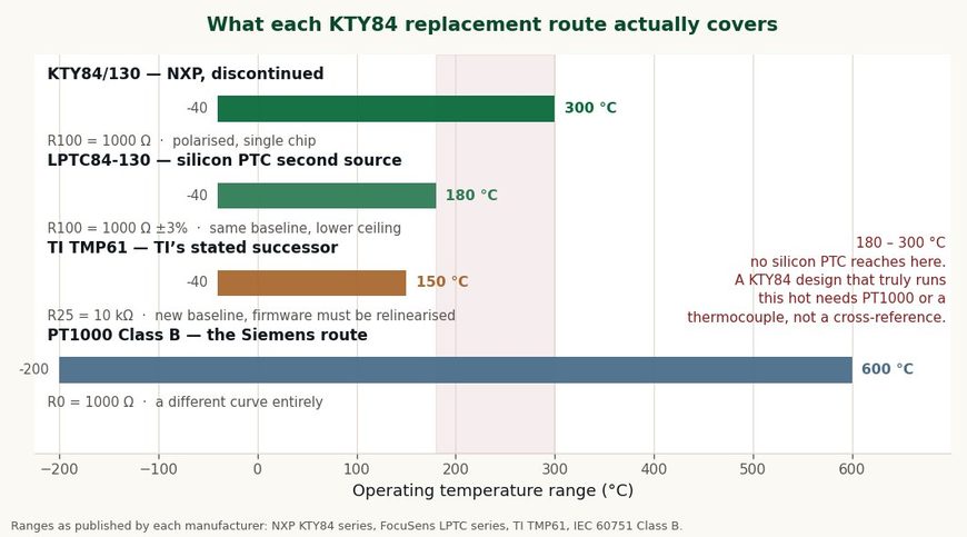
Four replacement routes and what each actually covers. The shaded band is the range a KTY84 design may be using and no silicon PTC can reach.
TI names the TMP6x family as the successor to KTY81 and KTY82, and TMP61 tops out at 150 °C, or 170 °C for the automotive grade. Silicon PTC second sources, ours included, generally stop at 180 °C. Only a platinum RTD or a thermocouple goes further.
So the first question is not which part matches the curve. It is whether the design genuinely operates above 180 °C, or whether 300 °C was headroom nobody ever used. Those two answers lead to completely different parts.
This one surprises people who have used KTY sensors for years without ever thinking about orientation. The reason they never had to is that they were using KTY81 or KTY82.
Philips built those two series as a twin-chip sensor: two elements in series with opposite polarity, so the resistance does not depend on current direction. KTY83 and KTY84 use a single chip, and they do depend on it. The original application note is blunt about it:
"KTY83 and 84 sensors are marked with a coloured band to indicate polarity. The published characteristics of the sensors will only be obtained if the current polarity is correct."
Philips, Silicon sensors for temperature application note.
| Series | Construction | Polarity matters | Package |
|---|---|---|---|
| KTY81 series | Twin chip, series opposed | No | SOD70 |
| KTY82 series | Twin chip, series opposed | No | SOT23 |
| KTY83 series | Single chip | Yes, coloured band | SOD68 |
| KTY84 series | Single chip | Yes, coloured band | SOD68 (DO-34) |
Construction differs across the KTY family, and so does whether orientation matters on the line.
The failure mode is not dramatic and that is what makes it expensive. A reversed KTY84 still produces a plausible resistance. It simply does not follow the published table, so the error shows up as a calibration problem months later rather than as a dead sensor at test.
If you are moving from KTY81 to a polarised part, or from a polarised part to an unpolarised one, the assembly instruction changes. Say so on the drawing rather than assuming the line will notice a coloured band that was never there before.
TI is direct about this in its own EOL note. TMP61 is a 10 kΩ part where KTY81 and KTY82 were 1 kΩ and 2 kΩ, and TI states that the software conversion has to be adjusted, recommending a fourth-order polynomial for the new curve.
That is not a scaling factor. The shape of a silicon PTC curve is not the shape of the KTY curve, so a lookup table or polynomial fitted to one will not serve the other even after the resistances are normalised.
Siemens hit the same wall when it moved its motors and spindles from KTY84-130 to PT1000, and the wording in its product note is unusually direct for a manufacturer document:
"The PT1000 is the alternative successor to be used in our motors and spindles ... the temperature characteristic is not compatible!!!"
Siemens, KTY to PT1000 product note.
One more thing changes with TMP6x that the word firmware hides. A KTY part is driven at a defined sense current; a TMP6x is read through a bias resistor and a voltage divider. The analogue front end is a different circuit, not only a different lookup table.
The one route that avoids a firmware change is a silicon PTC built to the same baseline as the original: same reference resistance, same reference temperature, same curve family. That is the only case where the existing lookup table survives untouched.
Shortage plus a known part number is the condition counterfeiters need, and KTY84 has both. The clearest public account comes from the electric-vehicle community, where these sensors sit in motor windings.
Parts sold as KTY84/130 at roughly a tenth of the genuine price track correctly up to about 1400 Ω, which is around 155 °C. Above that they turn over: resistance starts falling as temperature rises.
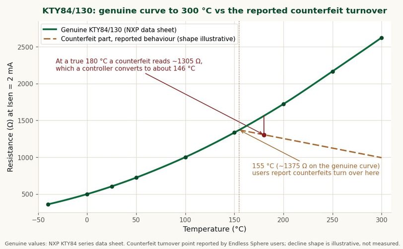
A sensor that reads correctly through the whole of a normal bench test, and lies exactly where the reading matters.
That behaviour is worse than a dead part. A winding at a genuine 180 °C reports a comfortable number, and the protection circuit that was supposed to trip does nothing. The sensor passes every test that stays below 155 °C.
Read it at room temperature, reverse the meter leads, then heat it past 200 °C and confirm the resistance is still climbing. Only the third check catches this failure, because a counterfeit tracks correctly below 155 °C and passes everything else.
The full procedure, with the acceptable band at every temperature and what each reading means, is in how to test a KTY84-130 with a multimeter. Community reports describing exactly this turnover are in the Endless Sphere thread on counterfeit KTY-84 sensors.
KTY84/130 and KTY84/150 are both rated -40 to +300 °C. They differ in accuracy, not in ceiling. NXP gives the /130 a temperature error of about ±4.9 K at 100 °C against about ±8.17 K for the /150.
The same convention runs through the rest of the KTY numbering, where the one-sided grades sit beside the symmetric ones. The full suffix decoding for the 1 kΩ and 2 kΩ families is in the KTY83-110 cross-reference guide.
Read through that convention, the counterfeit reports become coherent rather than puzzling. A device whose behaviour stops at 155 °C is not a low-accuracy KTY84, because no KTY84 ends at 155 °C.
If you cannot heat a sample safely to 200 °C, the fallback is documentation. Ask the supplier for the manufacturer data sheet for that exact part number and a certificate of conformity referencing it, and treat an equivalence claim on a listing as the marketing copy it is. The bench procedure is in how to test a KTY84-130 with a multimeter.
| Situation | Route | What changes |
|---|---|---|
| Peak sensing temperature stays below 150 °C | TMP6x or an equivalent silicon PTC | New base resistance, relinearise firmware |
| Peak stays below 180 °C | Silicon PTC on the same R100 = 1000 Ω baseline | Curve and lookup table can be kept |
| Peak is between 180 °C and 300 °C | PT1000, or a thermocouple above 600 °C | New curve, new wiring, new conversion |
| Original part was KTY81 or KTY82 | Check whether the replacement is polarised | Assembly drawing and line instruction change |
| Original part was KTY83 or KTY84 | Keep the polarity marking requirement | Verify the band exists on incoming parts |
For motor winding protection specifically, a linear silicon PTC and a switching PTC solve different problems, and mixing them up is its own class of error. The PTC motor winding protection guide covers the switching side, and the PTC thermistor guide explains why one name covers two device families.
Same curve, wider tolerance band. KTY84/130 is specified at 970-1030 Ω at 100 °C and the /150 at 950-1050 Ω. Counterfeit parts have been reported labelled /150 while being sold as /130.
No. Normalising the resistance does not change the shape of the curve. TI recommends a fourth-order polynomial for TMP6x precisely because the conversion is not a scale factor.
Yes. KTY83 and KTY84 are single-chip and polarised, and the published characteristics only hold with the correct current direction. KTY81 and KTY82 are twin-chip and orientation does not matter.
LPTC84-130 is built on the same R100 = 1000 Ω baseline at ±3 %, so an existing lookup table carries over.
Two differences are worth stating plainly. Its ceiling is 180 °C rather than 300 °C, and the body is DO-35 glass where the KTY84 is SOD68, also called DO-34, so check the bore or sleeve before assuming it drops in. Specifications are on the LPTC linear silicon PTC page.
If a design genuinely uses the range above 180 °C, we will say so and point at PT1000 rather than sell a part that cannot cover it.
color:#11181D;font-family:Helvetica Neue , Arial, sans-serif;font-size:medium;white-space:normal;background:#FAF9F4;border:1px solid #DDD8CB;border-left:4px solid #0A6B3B;border-radius:4px;padding:16px 18px;margin:22px 0;line-height:1.75;Where the replacement is a PT1000 rather than another silicon PTC, the drive input has to be told. A KTY84 element left on a PT1000-configured input under-reads by about 100 K and the overtemperature alarm never fires: what a drive reads with the wrong sensor has both directions in kelvin.No.1 XiSan Road, Electromechanical Industry Park , High&New Tech.Zone. Hefei,Anhui,China
тел : +86-551-69109668
Whatsapp : +86-13339100504
Эл. адрес : info@focusens.com
Skype : melodyliu520






 +86-551-69109668