Cold Junction Compensation: Why Thermocouples Read Low
Sep 25, 2026Cold junction compensation (CJC) corrects a thermocouple reading for the temperature of the point where the thermocouple wires meet the instrument's copper terminals. A thermocouple produces a voltage set by the temperature difference between its tip and that point,
so the instrument measures the terminal temperature, converts it to the equivalent thermocouple voltage, and adds that voltage before converting the total to temperature.
Without cold junction compensation, a Type K thermocouple at 100 °C with its terminals at 25 °C reads 75.9 °C, not 75 °C (in Fahrenheit, 212 °F with 77 °F terminals reads about 169 °F).
A Type T at 300 °C with the same 25 °C terminals reads 282.8 °C, only 17.2 K low. The error is close to the terminal temperature, but not equal to it, and wiring faults can push it high as well as low.
Reviewed by the Focusens Engineering Team, 24 September 2026.
Thermocouple reference tables give the voltage a thermocouple produces with its reference junction at 0 °C. The National Institute of Standards and Technology (NIST) ITS-90 thermocouple database publishes those tables and the reference functions behind them, and IEC 60584-1 standardises the same functions.
A field instrument never has a 0 °C reference, so it measures the real one and corrects for it.
Worked through for a Type K thermocouple with its tip at 400 °C and the instrument terminals at 30 °C, using the NIST Type K table:
Skip step 3 and 15.194 mV looks up as 371.5 °C, which is 28.5 K low rather than 30 K low.
The correction is made in millivolts, not in degrees. Beckhoff's thermocouple basics (EPP3314-0002 documentation) states that the compensation "is carried out with the voltages and not with the temperature". Adding 30 °C to 371.5 °C would give 401.5 °C, a 1.5 K error created by the arithmetic alone.
A thermocouple's sensitivity changes with temperature. Near room temperature Type K produces about 40.5 µV per kelvin; at 400 °C about 42.2 µV/K; at 1000 °C about 39.0 µV/K. Type T rises from about 40.7 µV/K at 25 °C to about 58.1 µV/K at 300 °C.
The voltage lost by ignoring the terminals is fixed by the terminal temperature, but the number of degrees it represents depends on the sensitivity at the tip. Every value in this section and the tables that follow is computed from the NIST ITS-90 reference functions,
which reproduce the published NIST tables to the last printed digit at every point we checked.
Type K and J with no compensation, displayed temperature (error in kelvin):
| Type | Terminals at | Tip 100 °C | Tip 200 °C | Tip 400 °C | Tip 800 °C | Tip 1000 °C |
|---|---|---|---|---|---|---|
| K | 10 °C | 90.4 (−9.6) | 190.1 (−9.9) | 390.6 (−9.4) | 790.3 (−9.7) | 989.8 (−10.2) |
| K | 25 °C | 75.9 (−24.1) | 174.9 (−25.1) | 376.3 (−23.7) | 775.7 (−24.3) | 974.4 (−25.6) |
| K | 40 °C | 61.2 (−38.8) | 159.7 (−40.3) | 361.7 (−38.3) | 760.9 (−39.1) | 958.9 (−41.1) |
| J | 25 °C | 76.4 (−23.6) | 177.0 (−23.0) | 376.8 (−23.2) | 780.2 (−19.8) | 978.5 (−21.5) |
Type T, E, N and S with no compensation, displayed temperature (error in kelvin):
| Type | Terminals at | Tip 100 °C | Tip 200 °C | Tip 300 °C | Tip 400 °C | Tip 1000 °C |
|---|---|---|---|---|---|---|
| T | 10 °C | 91.6 (−8.4) | 192.6 (−7.4) | 293.3 (−6.7) | 393.7 (−6.3) | above Type T range |
| T | 25 °C | 78.4 (−21.6) | 181.1 (−18.9) | 282.8 (−17.2) | 383.9 (−16.1) | above Type T range |
| T | 40 °C | 64.5 (−35.5) | 169.2 (−30.8) | 272.0 (−28.0) | 373.8 (−26.2) | above Type T range |
| E | 25 °C | 77.6 (−22.4) | 179.7 (−20.3) | 280.7 (−19.3) | 381.3 (−18.7) | 980.1 (−19.9) |
| N | 25 °C | 77.5 (−22.5) | 179.9 (−20.1) | 281.3 (−18.7) | 382.2 (−17.8) | 983.0 (−17.0) |
| S | 25 °C | 80.2 (−19.8) | 183.0 (−17.0) | 284.3 (−15.7) | 385.1 (−14.9) | 987.6 (−12.4) |
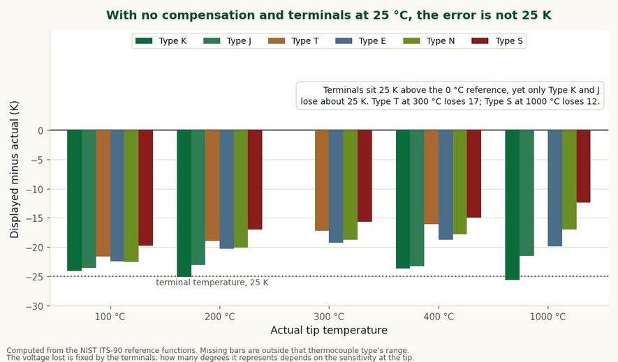
With the terminals 25 K above the reference, only Type K and J lose about 25 K.
Two things follow. A missing compensation always reads low when the terminals are above 0 °C, because the lost voltage is positive. And the rule of thumb that "no CJC means low by ambient" works for Type K and J but not for the others.
For Type K between 100 and 1000 °C the error stays within about 2 K of the terminal temperature. For Type T at 300 °C it is about 70% of the terminal temperature, and for Type S at 1000 °C about half.
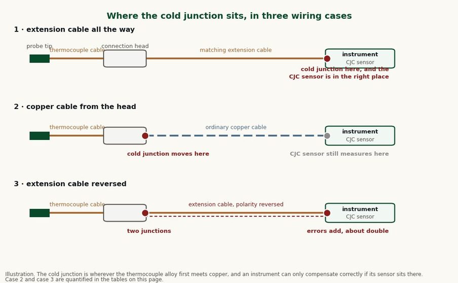
Illustration. The cold junction is wherever thermocouple alloy first meets copper.
The cold junction is the first point where the thermocouple alloy meets copper. Beckhoff describes it as the point "at the transition from the thermocouple to the copper contacts". An instrument can only compensate correctly if its temperature sensor sits at that point.
With thermocouple wire or matching extension cable all the way to the instrument, that point is the instrument's terminal block and the built-in sensor is in the right place. Run ordinary copper cable from a connection head to the panel and the transition moves to the connection head.
The instrument still measures its own terminals, so the compensation is applied for the wrong temperature and the reading is off by roughly the difference between the head and the panel.
Type K thermocouple with copper cable from the connection head to the instrument:
| Tip | Connection head | Instrument terminals | Displayed | Error |
|---|---|---|---|---|
| 400 °C | 60 °C | 25 °C | 365.9 °C | −34.1 K |
| 400 °C | 80 °C | 25 °C | 346.1 °C | −53.9 K |
| 800 °C | 90 °C | 30 °C | 740.0 °C | −60.0 K |
| 400 °C | 5 °C | 30 °C | 423.8 °C | +23.8 K |
| 200 °C | −10 °C | 25 °C | 234.7 °C | +34.7 K |
The last two rows are the outdoor case: a connection head colder than the panel makes the reading high, which is the opposite of what most people expect from a thermocouple fault.
This error moves with the weather and with process heat reaching the head, so it looks like drift rather than a wiring mistake. Eurotherm describes a controller that kept indicating its setpoint while the actual temperature slowly climbed, because the cable between head and controller was copper.
Where copper cable to the panel is unavoidable, a transmitter mounted in the connection head converts the signal there, so the compensation is measured where the cold junction is and the copper run carries a current signal instead of millivolts.
The effect depends on where the reversal is.
The signal inverts. With the terminals at 25 °C, and the reversal point also near 25 °C, a Type K tip at 50 °C reads about −0.6 °C and a tip at 100 °C reads about −55.8 °C.
A tip at 200 °C reads about −218 °C, which is below the −200 °C lower limit some modules set for Type K, so those show under-range or a sensor fault; a module that covers the full −270 °C Type K range,
such as the Siemens S7-1500 module listed further down, displays about −218 °C.
The giveaway is direction: the reading falls as the process heats up.
This case is harder to spot, because the reading still rises with the process. Two unwanted junctions form, one at the head and one at the terminals, and their errors add. Eurotherm puts the result at about twice the head-to-controller temperature difference and calls it worse than using copper. The NIST arithmetic agrees:
| Tip | Connection head | Instrument terminals | Displayed | Error |
|---|---|---|---|---|
| 400 °C | 60 °C | 25 °C | 331.6 °C | −68.4 K |
| 400 °C | 80 °C | 25 °C | 291.7 °C | −108.3 K |
| 800 °C | 90 °C | 30 °C | 680.7 °C | −119.3 K |
| 400 °C | 5 °C | 30 °C | 447.5 °C | +47.5 K |
| 200 °C | −10 °C | 25 °C | 268.8 °C | +68.8 K |
Type K. Compare each row with the copper-cable table above: the error is about twice as large.
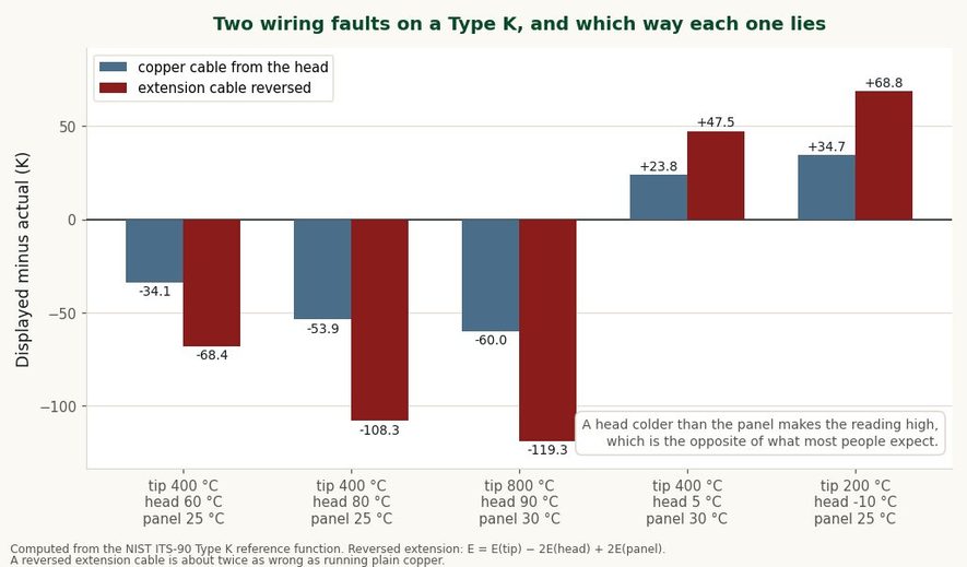
A reversed extension cable is about twice as wrong as plain copper, and both can read high when the head is colder than the panel.
Colour codes are a common cause. In North American extension cable the negative conductor is red, and other national colour codes differ again, so a technician following "red is positive" will reverse the pair.
Rockwell's manual for its 1769-IT6 thermocouple module warns that the wrong extension wire or incorrect polarity "will cause invalid readings".
When a programmable logic controller (PLC) and a handheld meter disagree on a thermocouple, the size and sign of the gap usually point to the cause:
| What you see | Likely cause | Quick check |
|---|---|---|
| PLC low by about the panel temperature | Compensation disabled, or set to a fixed 0 °C reference | Check the input's reference-junction setting |
| PLC high by about the panel temperature | Compensated twice: a signal conditioner or isolator in the loop already outputs a compensated millivolt signal and the input adds compensation again; or the handheld is the one not compensating | Check whether anything between the probe and the input already compensates, and check the handheld at a known temperature |
| Error changes with weather or with heat at the connection head | Copper cable between head and panel | Check the cable type from head to panel |
| Error about twice the head-to-panel difference | Extension cable reversed | Check polarity at both ends |
| Reading falls as the process heats | Thermocouple reversed | Swap the pair at the sensor |
| Error of tens of kelvin, growing with temperature | Wrong thermocouple type configured | Compare the configured type with the sensor's colour code or label |
A thread on r/PLC described this situation: a PLC reading 17 to 18 °C higher than a handheld meter on most points. A reply in that thread pointed out that a missing compensation reads low, so, if the handheld is accurate, a high reading rules it out.
When the gap is similar to room temperature, double compensation is worth checking early: with a Type K at 100 °C and compensation applied twice at 18 °C, the display shows 117.4 °C, and at 400 °C it shows 417.0 °C.
The wrong-type row produces larger and less even errors. With the terminals at 25 °C, a Type J thermocouple read as Type K shows about 258.5 °C at an actual 200 °C, and a Type K read as Type J shows about 157.3 °C.
A Type T read as Type K is the exception: at 100 °C it shows about 104.6 °C, close enough to pass a casual check.
Before any of this, confirm the handheld. Connect both instruments to the same thermocouple through a proper thermocouple connector, and check the handheld against a known temperature.
The instrument's terminal sensor has its own error, and it passes into the reading almost one for one. Manufacturers' figures:
| Module | Manufacturer's figure | Source |
|---|---|---|
| Omron NX-TS thermocouple input units | Cold junction compensation error ±1.2 °C, with the matching terminal-block sensor fitted | Omron specification |
| Siemens S7-1200 G2 SM 1231 TC (6ES7231-5QF50-0XB0) | ±1.5 °C at the cold connection point | Siemens datasheet |
| Siemens S7-1500 AI 8xU/I/RTD/TC ST, internal reference junction | Temperature error of internal compensation ±6 °C | Siemens equipment manual, p. 49 |
| Beckhoff EL3314, Type K with internal cold junction | ±3 °C total measurement uncertainty at 23 °C, which includes the compensation | Beckhoff product page |
For comparison, a Type K thermocouple to IEC 60584-1 Class 1 is allowed ±1.5 °C from −40 to 375 °C, and Class 2 is allowed ±2.5 °C from −40 to 333 °C. The reference measurement can contribute as much error as the sensor itself, and on some modules several times more.
The modules above offer alternatives to the internal sensor. The Siemens S7-1500 module lists an internal reference junction, a reference channel of the module, a fixed reference temperature and a dynamic reference temperature.
Beckhoff's EL3314 can be set to internal compensation, no compensation, or an external value supplied as process data. An external Pt100 at the terminal block, or a fixed reference where the terminals sit in a temperature-controlled enclosure, is a common route when the internal figure is too wide.
Where an RTD is used as the reference, its own lead-resistance error applies; see how 1 Ω of cable becomes 2.56 °C on a PT100.
With the terminals near 25 °C, a 1.5 K error in the reference junction reading becomes a 1.44 K error at a Type K tip at 400 °C, 1.56 K at 1000 °C, and 1.05 K at a Type T tip at 300 °C.
Short the thermocouple input with a copper jumper. With zero thermocouple voltage, an instrument that compensates correctly displays the temperature of its own terminals. If it displays 0 °C, compensation is off.
A plausible value does not prove the terminal sensor is present: the Rockwell 1769-IT6, for example, uses 25 °C or its last valid reading when a terminal-block sensor is missing and sets an open-circuit bit, so check the module's compensation diagnostic as well.
For a check of the whole loop, use a thermocouple calibrator connected with thermocouple-alloy leads, or put the probe in a stirred ice bath. At 0 °C a correctly compensated channel should read 0 °C within the combined tolerance of the sensor and the module.
To check the thermocouple itself before blaming the compensation, see how to test a thermocouple with a multimeter.
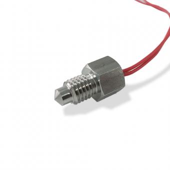
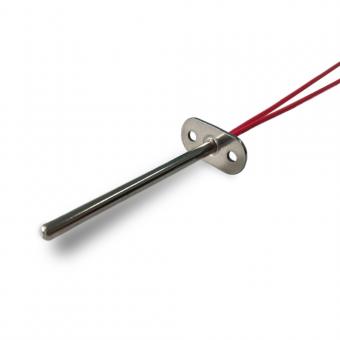
We make FWR series thermocouple sensors in Types J, K, T, E, N and S, with grounded or ungrounded junctions, PTFE, silicone, fibreglass, braided or mineral-insulated MgO cable, and a choice of mountings.
When you send an enquiry, state the thermocouple type, grounded or ungrounded junction, cable insulation, and whether the probe ends in a junction box (without, anti-spray or waterproof) or in a cable.
Wherever the thermocouple alloy first meets copper is where the cold junction ends up, so that last choice decides where your compensation has to be measured.
Browse the thermocouple sensor range, including the T/K/J general-purpose thermocouple and the K-type high-temperature thermocouple. For choosing between sensing technologies, see our comparison of NTC, PTC, RTD and thermocouple sensors and thermocouple vs thermistor.
Cold junction compensation is the correction an instrument applies for the temperature of the point where the thermocouple meets copper. The instrument measures that temperature, converts it to the equivalent thermocouple voltage and adds it to the measured voltage, so the reading reflects the tip temperature alone.
To calculate cold junction compensation, look up the voltage for the terminal temperature in the reference table for your thermocouple type, add it to the measured voltage, then look up the total.
For Type K at 400 °C with terminals at 30 °C: 15.194 mV + 1.203 mV = 16.397 mV, which is 400 °C. Add voltages, not degrees.
Cold junction compensation is required because a thermocouple measures a temperature difference, not a temperature. Without a known reference, the same tip temperature gives different readings as the terminals warm and cool; for Type K, each kelvin of terminal change moves the reading by about one kelvin.
An ice-point reference at 0 °C can replace electronic compensation. It is how the reference tables are defined and is still used in calibration laboratories, but it is impractical for permanent installations, which is why instruments compensate electronically.
An RTD or thermistor does not need cold junction compensation. Both measure resistance, not a voltage generated between two junctions; their equivalent concern is lead-wire resistance.
No.1 XiSan Road, Electromechanical Industry Park , High&New Tech.Zone. Hefei,Anhui,China
тел : +86-551-69109668
Whatsapp : +86-13339100504
Эл. адрес : info@focusens.com
Skype : melodyliu520






 +86-551-69109668